In high-power lighting systems, thermal management is an important factor affecting the reliability and service life of both LED drivers and LED modules. Operating a driver close to its maximum rated power at elevated temperatures can increase component stress, reduce available output power, and accelerate long-term component degradation. Engineers and procurement teams constantly balance the demand for maximum lumen output against the physical limits of electronic components operating in high-ambient environments. Operating a driver continuously at or near its maximum rated power under elevated-temperature conditions can increase thermal stress and may shorten component life. Whether thermal operation affects warranty coverage depends on the manufacturer's specified operating conditions and warranty terms.
Specifying the correct power supply requires a rigorous understanding of LED driver thermal derating. You must know exactly how manufacturers implement current foldback to protect internal components. These mechanisms directly dictate both actual output power and the useful life of the entire lighting system. Proper implementation prevents thermal runaway while maintaining baseline illumination, ensuring your luminaire survives harsh field conditions.
Key Takeaways
Temperature Has a Major Impact on Component Life: For many aluminum electrolytic capacitors, estimated useful life decreases as operating temperature increases. A commonly used approximation is that capacitor life may decrease by about half for each 10°C increase, but the actual relationship depends on the capacitor's specifications and life model.
Derating Can Protect the Driver Under High Thermal Stress: Depending on the driver design, thermal derating may progressively reduce output current or power when specified temperature limits are approached. The exact derating profile should always be confirmed from the manufacturer's datasheet. preventing catastrophic failure at the cost of temporary lumen reduction.
$T_c$ (Case Temperature) Is an Important Design Metric: Many LED driver manufacturers specify a maximum case temperature and a corresponding derating curve. Engineers should evaluate the specified $T_c$ measurement point together with ambient temperature, installation conditions, and the manufacturer's thermal data. Evaluating a driver requires looking past ambient temperature claims and analyzing the manufacturer’s derating curve relative to the maximum allowable case temperature ($T_c$) at the designated measurement point.
System-Level Design is Mandatory: A driver's thermal performance cannot be evaluated in isolation; enclosure design, heat sinking, and NTC thermistor integration are critical for realizing the datasheet's promised lifetime.
Table of Contents
Toggle
How LED Driver Thermal Derating Works
Defining Thermal Derating in Power Electronics
Thermal derating involves operating an electronic device below its maximum rated limits. Engineers reduce the allowable current, voltage, or power as ambient temperatures rise. This practice increases component reliability and accommodates harsh operating environments without triggering immediate hardware failure. In power electronics, heat generation is unavoidable due to switching losses in MOSFETs, conduction losses in diodes, and core losses in magnetic components like inductors and transformers.
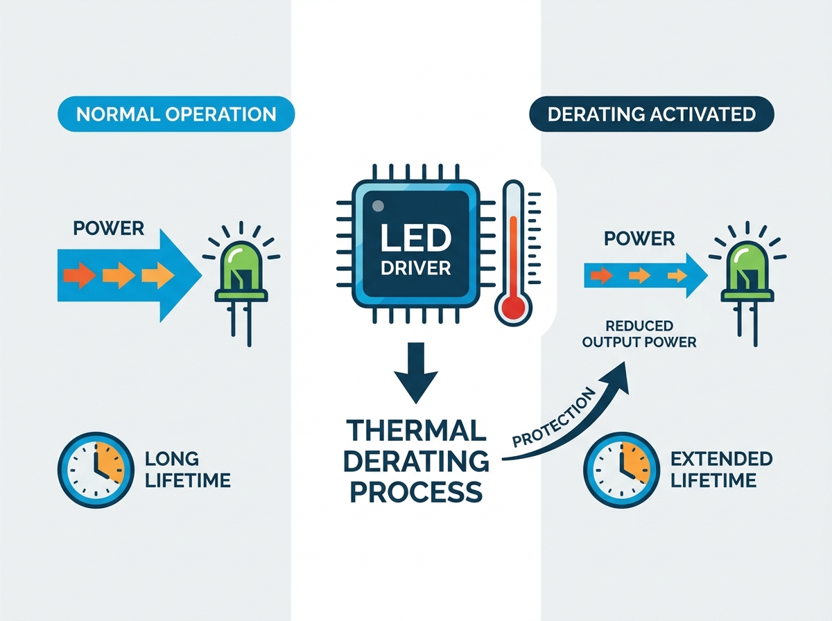
An LED driver thermal derating profile functions as a dynamic protection circuit. It actively monitors internal heat levels. When temperatures approach critical thresholds, the control circuitry intervenes by scaling back the power delivered to the load. This prevents semiconductor junctions from melting and electrolytic capacitors from venting gas. The derating curve provides a strict mathematical boundary for safe operation, ensuring the power supply does not destroy itself when installed in poorly ventilated fixtures.
Junction Temperature ($T_j$) vs. Case Temperature ($T_c$)
Understanding thermal limits requires distinguishing between internal and external temperatures. Junction temperature ($T_j$) refers to the actual semiconductor material inside components. This is the exact microscopic location where heat originates during electrical switching. Case temperature ($T_c$) is the measurable temperature on the external housing of the driver. Heat travels from the semiconductor junction, through the component packaging, into the PCB, and finally out to the driver case.
Manufacturers specify a maximum $T_c$ point on the driver housing. This specific location correlates directly with the hottest internal components, usually the main switching MOSFET or the primary electrolytic capacitor. Measuring temperature anywhere else on the driver yields inaccurate data and creates a false sense of security. Exceeding the maximum $T_c$ limit triggers the derating protocol. The thermal resistance ($\theta_{JC}$) between the junction and the case dictates how quickly the driver must react to prevent internal damage.
Internal Thermal Protection and External Temperature Feedback
LED drivers can use different thermal management strategies depending on their design. Internal protection may monitor temperatures within the power supply and reduce output power or shut the driver down when specified limits are reached.
Some specialized LED driver systems also support external temperature sensing. An NTC thermistor can be placed on an LED module or another monitored location when the driver is specifically designed to accept external temperature feedback. In such systems, the driver can adjust output current based on the detected temperature.
However, an external NTC should not be assumed to be a standard feature of every LED driver. Engineers should verify the supported sensor type, wiring method, temperature range, and control behavior in the product datasheet. Internal driver protection relies on IC-level thermal derating techniques. Advanced LED driver integrated circuits feature on-chip temperature sensors. These sensors provide autonomous, precise thermal shutdown capabilities by monitoring the silicon substrate directly. If the IC overheats, it reduces the switching frequency or duty cycle, instantly lowering the power output.
External protection involves the driver responding to outside sensors. Engineers mount a Negative Temperature Coefficient (NTC) thermistor directly on the LED module or the primary heat sink. The driver monitors the resistance of this external NTC. As the LED array heats up, the NTC resistance drops predictably. The driver reads this analog change and reduces output current accordingly. This protects the LEDs even if the driver itself remains relatively cool inside a separate compartment.
When an LED driver supports external NTC sensing, engineers should verify the compatible NTC specification, sensor placement, wiring requirements, temperature thresholds, and control response before integrating it into the luminaire.
How LED Driver Thermal Derating Affects Output Power
Quasi-Linear Current Reduction (Foldback)
Depending on the protection strategy, an LED driver may reduce output current, reduce output power, enter a protection mode, or shut down when its specified thermal limits are reached.
Drivers with thermal foldback gradually reduce output under certain high-temperature conditions, allowing the system to continue operating at reduced power. Other designs may use thermal shutdown when the temperature exceeds a defined protection threshold.
The exact response should therefore be verified from the manufacturer's protection and derating specifications rather than assumed from the driver category. Abrupt shutdowns cause total darkness, creating severe safety hazards in industrial and outdoor environments. Instead, the control circuit initiates a quasi-linear reduction in output current. This process is known as thermal foldback. The driver gradually lowers the current as the temperature continues to climb, creating a smooth transition rather than a jarring blackout.
This current foldback directly reduces the wattage delivered to the LED array. Lower wattage means less heat generation at both the driver and the LED module. The system stabilizes at a lower power level, finding a thermal equilibrium. It prevents thermal runaway while maintaining baseline illumination. Once the ambient environment cools down, the driver automatically restores the current to its nominal setpoint without requiring a manual reset.
Driver Condition
Possible Response
Within rated thermal range
Full rated output may be available
Approaching thermal limit
Output may be reduced depending on the design
Thermal limit exceeded
Protection or shutdown may occur
Temperature returns to normal
Output behavior depends on the driver’s control strategy
Impact on Lumen Maintenance and Dimming
Thermal derating has highly visible effects on the end-user experience. In high-heat environments, such as foundries or unconditioned warehouses during summer, the fixture may exhibit unintentional dimming. Facility managers often mistake this protective dimming for a hardware malfunction. Reducing driver output current generally reduces LED power and luminous output, although the relationship between LED current and luminous flux is not necessarily perfectly linear. This ensures the fixture survives the heat wave, but it compromises temporary lighting levels on the floor.
Derating also interacts with programmed dimming protocols like 0-10V, DALI, or PWM. Control conflicts can arise if thermal limits are breached. For example, a DALI controller might demand 100% output based on a scheduled scene. However, the thermal protection circuit overrides this command, capping the output at 60% due to high case temperatures. When thermal protection is activated, the driver's internal protection logic may limit or override the requested output level to keep operation within its specified thermal limits. to prevent catastrophic failure.
Trade-offs: Peak Power vs. Thermal Stability
Lighting designers face a constant engineering trade-off. They must evaluate the desire for peak brightness against the need for thermal stability. Driving LEDs at their maximum specified current yields the highest lumen output per chip. However, it generates maximum heat. This pushes the driver closer to its thermal limits, reducing the safety margin and increasing the likelihood of triggering the foldback circuit during normal operation.
Driving LEDs at a lower nominal current maintains a wider thermal safety margin. It requires more LED chips to achieve the same total lumen output, increasing upfront board costs. Yet, this conservative approach drastically improves system reliability and efficacy. Engineers must analyze the expected ambient temperatures of the installation site and balance the initial lumen requirements against long-term thermal stability.
How Thermal Derating Affects LED Driver Lifetime
Electrolytic Capacitor Degradation (The Arrhenius Equation)
Electrolytic capacitor degradation is a common lifetime-limiting mechanism in many power supply designs, although the dominant failure mechanism varies with driver topology, component selection, operating conditions, and construction. These components rely on liquid electrolytes to function. Sustained high temperatures cause this liquid to vaporize and escape through the rubber seal at the base of the capacitor. As the electrolyte dries out, the capacitor loses capacitance. The driver eventually fails to regulate voltage properly, leading to flickering or total failure.
The Arrhenius equation governs this chemical degradation process. In practical engineering terms, this translates to the 10°C rule. For many aluminum electrolytic capacitors, a commonly used lifetime estimation rule assumes that useful life approximately doubles for every 10°C reduction in the capacitor's operating temperature, within the manufacturer's specified temperature and lifetime model. Operating a driver at an internal temperature of 85°C instead of 75°C drastically alters its lifespan. For example, if a capacitor manufacturer's life model specifies 50,000 hours at 75°C and follows a 10°C life-halving approximation, the estimated life at 85°C would be approximately 25,000 hours. Actual life must be calculated according to the capacitor manufacturer's specified life model. This exponential decay makes thermal management the single most critical factor in driver longevity.
Beyond Capacitors: Multiple Component Degradation
While capacitors are the weakest link, sustained thermal stress accelerates the degradation of other critical components. MOSFET $R_{DS(on)}$ generally increases with junction temperature, which can increase conduction losses and further contribute to heat generation. Thermal design therefore needs to maintain adequate margin under the expected operating conditions. Optocouplers, used for galvanic isolation and voltage feedback, suffer from Current Transfer Ratio (CTR) degradation when exposed to chronic heat, which can reduce feedback performance and affect long-term regulation reliability.
Printed Circuit Board (PCB) solder joints also fail due to thermal cycling fatigue. As the driver heats up during operation and cools down when turned off, different materials expand and contract at different rates. This Coefficient of Thermal Expansion (CTE) mismatch places severe mechanical stress on the solder joints. Over thousands of cycles, micro-cracks form. These cracks eventually sever the electrical connection, causing intermittent faults or total failure.
Output Voltage Ripple and Component Stress
Continuous thermal cycling degrades the capacitor's Equivalent Series Resistance (ESR). As the electrolyte evaporates, the ESR increases significantly. A higher ESR means the capacitor can no longer filter high-frequency switching noise effectively. This leads to increased peak-to-peak output voltage ripple, increasing output ripple and potentially affecting LED current stability and lighting performance.
Increased voltage ripple stresses the LED array. LEDs are current-driven devices, and excessive ripple causes micro-fluctuations in brightness, often visible as high-frequency flicker. More importantly, high ripple current generates additional internal heating within the LEDs themselves. The degraded driver actively accelerates the failure of the LED module. Maintaining strict thermal limits prevents this cascading failure mechanism from destroying the entire luminaire.
MTBF (Mean Time Between Failures) vs. Useful Life
Engineers often confuse statistical MTBF with actual useful life. MTBF is a statistical calculation often derived from standards like MIL-HDBK-217 or Telcordia SR-332. It predicts the failure rate of a large population of devices over time. A driver might boast an MTBF of 2 million hours. This does not mean a single driver will last 200 years; it simply means the random failure rate during its normal operating life is very low.
Useful life is based on actual thermal wear-out mechanisms. It represents the physical time it takes for a specific component, usually the electrolytic capacitor, to degrade beyond usable limits. Evaluators must prioritize useful life curves provided by manufacturers over generic MTBF numbers. Useful life curves plot expected hours against specific $T_c$ measurements, giving you actionable data for warranty calculations.
Metric
Definition
Practical Use
MTBF
Statistical reliability metric describing expected failure behavior of a population
Reliability analysis and system-level planning
Useful Life
Expected operating period before specified wear-out mechanisms reach defined limits
Lifetime estimation and product qualification
How to Choose LED Drivers for High-Temperature Applications
Analyzing Manufacturer Derating Curves
Reading a datasheet derating curve is a fundamental skill for lighting engineers. These graphs typically plot Load Percentage on the Y-axis against Ambient Temperature ($T_a$) or Case Temperature ($T_c$) on the X-axis. A well-documented driver should provide a clear derating curve showing the allowable load at different ambient or case temperatures. The applicable temperature range varies by product and should be verified from the datasheet before the curve slopes downward.
Engineers must look for specific red flags during evaluation. Steep drop-offs at standard operating temperatures indicate poor internal thermal design or undersized heat sinks. A lack of specified $T_c$ measurement points renders the curve useless for real-world validation. If the datasheet only provides $T_a$ curves, it ignores the thermal reality of the luminaire enclosure. Always demand $T_c$-based derating data to ensure accurate thermal modeling.
Component-Level Scrutiny
Validating a manufacturer's thermal claims requires evaluating the internal Bill of Materials (BOM). The selection of highly reliable components dictates actual field performance. Many power supply designs use 105°C-rated electrolytic capacitors, while higher-temperature applications may require components with higher temperature ratings depending on the expected internal operating temperature and required lifetime.
Scrutinizing the BOM ensures the driver matches the datasheet promises. If a manufacturer claims a 100,000-hour life at a $T_c$ of 80°C, but uses cheap 85°C-rated capacitors, the math fails. Requesting component specifications from the supplier is a critical step. Engineers should evaluate capacitor manufacturers based on rated lifetime, temperature rating, ripple-current capability, reliability data, and application suitability rather than country of origin alone.
Active vs. Passive Thermal Management Features
Driver construction heavily influences thermal dissipation. Potted drivers feature electronics encapsulated in a thermally conductive compound, usually silicone or epoxy. This potting material eliminates air gaps inside the housing. It transfers heat efficiently from the hot components directly to the outer metal case. Thermally conductive potting compounds can improve heat transfer from selected components to the enclosure and may also improve vibration and environmental resistance. However, thermal performance depends on the compound's thermal conductivity, construction, housing design, and overall heat path, often reaching 1.5 to 3.0 W/m·K, and provide excellent vibration resistance compared to non-potted alternatives.
Advanced applications require programmable thermal foldback features. Industrial or automotive lighting systems face extreme temperature fluctuations. Programmable drivers allow engineers to set custom derating thresholds via software. They can define exactly when current reduction begins and how steep the foldback curve should be. This customization ensures the driver responds perfectly to specific environmental constraints without relying on generic factory defaults.
Scalability and Compliance Standards
Thermal derating capabilities must align with stringent industry standards. For commercial, industrial, and outdoor lighting, thermal should focus on the applicable product standards, manufacturer's derating curves, component ratings, enclosure conditions, and application-specific environmental requirements. Meeting these standards requires robust thermal design, high-grade components, and highly predictable derating behavior.
Standardizing on drivers with robust thermal profiles reduces SKU proliferation. A single, well-designed driver model can serve multiple fixture types across diverse deployment environments. Selecting a driver with an appropriate operating-temperature range and clearly defined derating behavior can allow a product platform to serve a wider range of applications, provided each installation remains within the specified limits by dynamically adjusting its output. This standardization simplifies inventory management, reduces engineering qualification time, and drastically reduces warranty claims related to thermal failures.
Common LED Driver Thermal Design Risks and How to Avoid Them
Misinterpreting Datasheet Specifications
A common engineering error involves assuming a driver can operate at 100% load at the maximum stated ambient temperature. Datasheets often highlight a maximum $T_a$ of 50°C on the front page. However, the derating curve buried on page four might show load reduction starting at 40°C. Ignoring the curve leads to overloaded drivers, triggered foldback circuits, and premature field failures.
Consider a calculation example. A 100W driver is installed in a sealed enclosure where the internal ambient air reaches 55°C due to solar loading. The derating curve dictates a 20% load reduction at 55°C. The driver can now only safely supply 80W. If the LED array demands 95W, the driver will overheat and shut down. Engineers must derate the load based on actual expected enclosure temperatures, not the ambient temperature of the room.
Enclosure and Heat Sink Design Considerations
The physical realities of installation dictate thermal performance. A driver performing perfectly on an open test bench will fail if installed improperly. Installing a driver inside a sealed or poorly ventilated luminaire can significantly increase the internal operating temperature. The enclosure's IP requirements, thermal path, mounting method, and available heat dissipation must therefore be considered together. Without proper thermal coupling to the external environment, the internal air temperature skyrockets, pushing the driver past its $T_c$ limit within hours.
Mitigation strategies require careful mechanical design. Utilize thermal gap pads to bridge the space between the driver case and the heavy metal luminaire housing, turning the entire fixture into a heat sink. Strategically place the driver in a separate compartment away from the LED heat sink to avoid absorbing external heat. Integrate external NTC thermistors to monitor the LED module and force the driver to derate before ambient enclosure temperatures become critical.
Testing and Validation (Continuous vs. Cycled)
Rigorous testing during the luminaire prototyping phase is non-negotiable. Relying solely on datasheet calculations leaves massive blind spots. Physical thermal testing validates the enclosure design and confirms the driver's derating behavior under actual load. Engineers must attach thermocouples to the exact $T_c$ point specified by the manufacturer and measure it directly during these tests.
Differentiating between steady-state and cycled testing is crucial. Steady-state testing applies continuous power until temperatures stabilize, verifying absolute maximums. Power/thermal cycled testing repeatedly turns the unit on and off while varying ambient temperatures in an environmental chamber. Cycled testing more accurately simulates real-world environmental stresses. It exposes thermal cycling fatigue in solder joints and accelerates multiple component degradation.
Install the driver inside the final production luminaire housing.
Attach thermocouples to the driver $T_c$ point and the LED array $T_j$ point.
Place the entire luminaire inside a thermal chamber set to the maximum expected ambient temperature.
Run the fixture at 100% load and monitor the time it takes to trigger the thermal foldback circuit.
Verify that the current reduction matches the manufacturer's published derating curve.
Conclusion
Take the following actionable steps to secure your lighting system designs and prevent premature thermal failures:
Audit your current luminaire thermal designs to ensure drivers operate at least 10°C below their maximum $T_c$ limits during normal operation.
Request detailed reliability data, specifically useful life curves and capacitor BOMs, from driver manufacturers before approving them for production.
Secure evaluation samples and execute in-situ power and thermal cycled testing within the actual sealed fixture housing.
Where supported by the driver design, consider external temperature sensing for LED modules operating in demanding thermal environments.
For lighting projects that require stable dimming performance and reliable power delivery across diverse operating conditions, Zhuhai Shengchang Electronics provides intelligent dimmable LED driver solutions backed by extensive R&D and manufacturing experience. Under the SURETRON brand, the company develops LED driver and intelligent lighting control solutions for residential, commercial, industrial, and outdoor lighting applications.
FAQ
Q: What is the difference between ambient temperature ($T_a$) and case temperature ($T_c$) in LED drivers?
A: Ambient temperature ($T_a$) is the temperature of the air surrounding the driver. Case temperature ($T_c$) is the physical temperature measured at a specific point on the driver's external housing. $T_c$ is an important practical measurement point specified by many LED driver manufacturers, but it does not directly represent the junction temperature of every internal component. Engineers should use the manufacturer's specified measurement point and thermal data when evaluating operating limits and is used to trigger thermal derating protocols.
Q: How does the 10°C rule apply to LED driver lifetime?
A: The 10°C rule is derived from the Arrhenius equation. It states that for A commonly used approximation for some aluminum electrolytic capacitors is that estimated life decreases by about half for each 10°C increase in operating temperature. However, this is not a universal rule for the entire LED driver. Actual driver lifetime depends on the components, thermal conditions, operating profile, and manufacturer's reliability model. This primarily affects the electrolytic capacitors inside the driver, accelerating electrolyte evaporation and causing premature failure.
Q: Why does my LED fixture dim automatically in hot environments?
A: This is intentional thermal foldback. When the driver or LED module reaches a critical temperature threshold, the protection circuit reduces the output current. This lowers the wattage and heat generation, preventing catastrophic hardware failure. The fixture will return to full brightness once the environment cools down.
Q: Can LED driver thermal derating prevent system failure entirely?
A: Thermal derating significantly reduces the risk of sudden catastrophic failure by preventing thermal runaway. However, it cannot stop the slow, long-term degradation of components caused by sustained high temperatures. Operating continuously in a derated state still accelerates wear-out mechanisms over time.
Q: How do NTC thermistors work with LED driver thermal derating?
A: An NTC (Negative Temperature Coefficient) thermistor is a resistor whose resistance decreases as temperature increases. In LED driver systems that support external NTC sensing, the thermistor can be mounted at the specified monitoring location, such as an LED module or heat sink. The driver measures the resistance change and can adjust output according to its programmed thermal-control strategy. If the array overheats, the driver detects the resistance drop and actively reduces output current to protect the LEDs.
Q: How do I calculate the actual useful life of an LED driver from its datasheet?
A: Ignore generic MTBF numbers. Locate the "Useful Life vs. $T_c$" graph in the datasheet. Measure the actual case temperature ($T_c$) of the driver while it operates inside your specific luminaire enclosure. First identify the manufacturer's useful-life model and the specified measurement point. Then measure the actual temperature under the intended load and installation conditions. The measured value can be compared with the manufacturer's useful-life curve to estimate the expected life of the relevant components. Actual system lifetime may differ because other components and operating conditions also contribute to reliability.