LED driver topology dictates fixture safety, thermal performance, and physical size. Lighting designers and manufacturers face a constant engineering dilemma. They must balance stringent electrical safety standards against market demands for higher luminous efficacy, miniaturized form factors, and lower Bill of Materials costs. Preventing shock hazards remains a primary design constraint. However, achieving ultra-slim luminaire profiles requires eliminating bulky internal components.
This guide provides a technical framework for evaluating the trade-offs between an isolated vs non-isolated LED driver. Specifiers can use this information to match the correct power supply architecture to their specific fixture enclosure. You will learn how to align driver topology with control systems and application environments effectively.
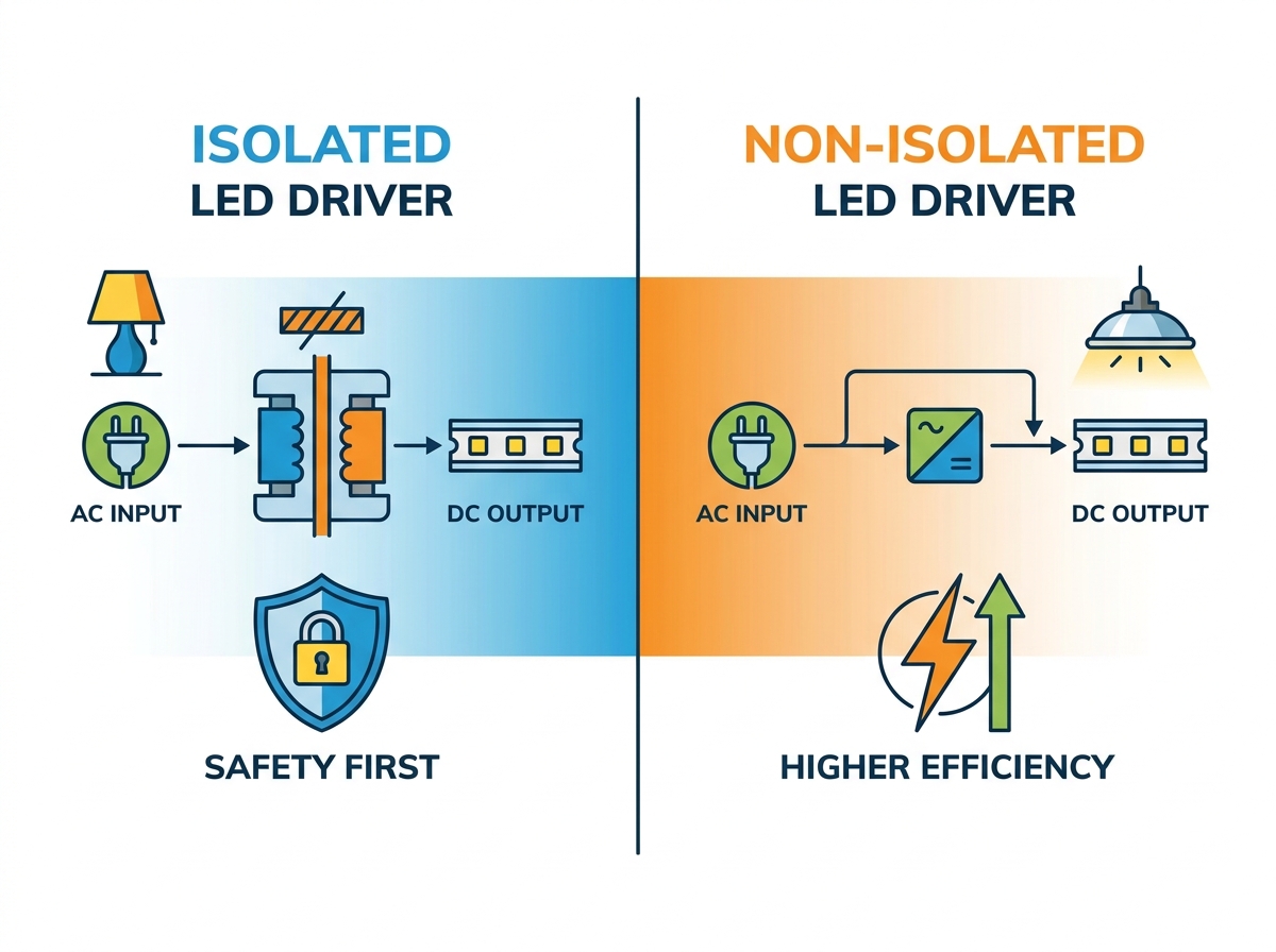
Safety vs. Efficiency Trade-off: Isolated drivers utilize galvanic isolation to separate high-voltage inputs from outputs, prioritizing safety, whereas non-isolated drivers eliminate the transformer to maximize electrical efficiency and reduce size.
Form Factor Constraints: Non-isolated designs require fewer internal components, making them the default choice for space-constrained applications like T8 LED tubes and compact linear fixtures.
Compliance and Enclosure Dependency: The choice between topologies dictates the physical design of the luminaire; Non-isolated LED drivers require the luminaire design to provide appropriate insulation, creepage and clearance, touch protection, and other safeguards required by the applicable safety standards.
Control and Dimming Integration: Isolated drivers offer inherently safer and simpler integration with low-voltage dimming controls (0-10V, DALI), preventing ground loops and protecting end-users at the switch.
Cost Implications: Isolated drivers carry a higher initial component cost due to complex magnetics, but often reduce the need for secondary physical safety barriers required in non-isolated fixture designs.
Table of Contents
Toggle
Isolated vs Non-Isolated LED Drivers: How They Work
The Mechanics of an Isolated LED Driver
Galvanic isolation forms the foundation of this driver topology. These circuits utilize a high-frequency transformer to transfer power magnetically. No direct electrical connection exists between the AC input and the DC output. This physical separation prevents high-voltage mains current from crossing over to the secondary circuit. The transformer acts as an absolute barrier against dangerous electrical faults. When a massive voltage spike hits the primary side, the physical gap prevents it from instantly destroying the secondary components.
The primary function involves stepping down high line voltage. Drivers take 120V or 277V AC inputs and convert them to a safe, low DC voltage. The magnetic transfer inherently blocks DC pathways. This ensures that only the regulated, safe current reaches the sensitive LED array. Engineers rely on this mechanism to protect both the light engine and the end-user. The printed circuit board (PCB) layout physically separates the primary and secondary traces, maintaining strict creepage and clearance distances.
Typical components include high-frequency transformers, Y-capacitors for electromagnetic interference (EMI) filtering, and optocouplers. Optocouplers manage the feedback loop across the isolation barrier. They transmit voltage regulation data using light rather than electrical wiring. Enhanced dielectric barriers provide additional insulation around the magnetic cores. These components collectively ensure strict adherence to electrical safety standards. You will often see potting compounds used in these drivers to further enhance thermal transfer and dielectric strength.
The Mechanics of a Non-Isolated LED Driver
Non-isolated circuits utilize a direct-drive approach. The input and output stages share a common electrical ground. In a non-isolated topology, the output is not galvanically isolated from the input mains. Depending on the circuit architecture, the LED output may therefore remain at a hazardous potential relative to earth. This shared ground path means that high voltage is present throughout the entire driver board. Any fault on the input side can immediately transfer to the output terminals. If the switching transistor fails short, full rectified mains voltage hits the LED string instantly.
These drivers rely on inductors rather than transformers. Engineers utilize buck, boost, or buck-boost topologies to regulate current. A buck converter steps down voltage using a switching transistor, a freewheeling diode, and an inductor. The inductor stores energy during the switch's on-time and releases it during the off-time. Some designs bypass switching altogether. They use linear regulator integrated circuits (ICs) to manage current flow. This method simplifies the power conversion process significantly, stripping the circuit down to bare essentials.
Component reduction defines the non-isolated architecture. The absence of bulky magnetic isolation components shrinks the circuit board. Designers eliminate heavy transformers and complex optocoupler feedback loops. The resulting driver is lightweight, highly compact, and easier to manufacture at scale. This simplicity drives widespread adoption in specific lighting categories where physical space is the absolute limiting factor.
Isolated vs Non-Isolated LED Drivers: Key Differences
Electrical Safety and Shock Hazard Mitigation
Direct-drive circuits carry inherent high-voltage surge risks. Fault conditions can easily reach the LED board. A failure in a non-isolated driver sends mains voltage directly to the light engine. This creates a severe shock hazard if the fixture housing is compromised. Installers face risks if they touch the LED array while the circuit remains energized. Field technicians must treat every component on a non-isolated board as live.
Luminaire classification dictates safety requirements. Class I fixtures rely on a physical earth ground to mitigate shock risks. Class II fixtures utilize double insulation instead of a grounding wire. The outer plastic or polycarbonate shell serves as the only barrier between the user and lethal voltage. You cannot use a non-isolated driver in a metal housing unless the LED board itself features massive dielectric insulation, which defeats the purpose of a cheap, compact design.
Isolated drivers provide inherent safety advantages. The transformer prevents mains voltage from reaching touchable surfaces. End-users or installers might contact the LED module or metallic heat sink during routine maintenance. Galvanic isolation ensures these components remain at a safe, low voltage. This makes isolated topologies mandatory for fixtures with exposed metallic parts. If a wire chafes against an aluminum extrusion, the isolated driver ensures the extrusion does not become a lethal shock hazard.
Power Efficiency, Thermal Dissipation, and Reliability
Conversion losses vary significantly between topologies. Non-isolated drivers typically achieve 90% to 95% electrical efficiency. Isolated drivers often peak between 85% and 90%. The high-frequency transformer causes this efficiency drop. Magnetic core losses (hysteresis and eddy currents) and copper winding resistance consume energy. Direct-drive circuits avoid these specific losses entirely by passing current directly through an inductor or linear IC.
Thermal management requirements scale with efficiency. Higher efficiency in non-isolated drivers reduces internal heat generation. Less wasted energy means cooler operating temperatures within the luminaire housing. Engineers can specify smaller heat sinks for non-isolated designs. This thermal advantage allows for tighter packaging in compact fixture designs. However, the heat generated by the LEDs themselves still requires management.
Thermal profiles heavily impact Mean Time Between Failures (MTBF). Electrolytic capacitors represent the weakest link in LED driver lifespans. Heat accelerates the evaporation of the liquid electrolyte inside these capacitors. For many aluminum electrolytic capacitors, a commonly used rule of thumb is that reducing operating temperature by approximately 10°C can roughly double expected lifetime, although the actual relationship depends on the capacitor specification and operating conditions.Cooler non-isolated designs can extend capacitor life. However, isolated drivers protect these sensitive components from grid surges, balancing the overall reliability equation. Field data shows that isolated drivers survive dirty power grids far longer than their non-isolated counterparts.
Dimming Compatibility and Control Systems Integration
Integrating low-voltage networks requires careful engineering. Dimming performance and control-system safety depend on how the control interface is electrically isolated and implemented, rather than on driver topology alone. The shared ground in direct-drive circuits can cross-contaminate the dimming network. This introduces mains-voltage noise into sensitive digital control lines. Ground loops cause erratic dimming behavior, ghosting, and potential equipment failure.
Safety in networked controls demands strict isolation. Isolated drivers serve as the industry standard for smart lighting. The transformer ensures that low-voltage control wires remain safe to touch. Installers can wire 0-10V switches without risking electrocution. Galvanic isolation blocks mains-voltage interference, guaranteeing stable and predictable dimming performance across large commercial installations.
Output Ripple Current and Flicker Performance
Power quality outputs differ based on the regulation method. The absence of a transformer can lead to higher output ripple current. Non-isolated designs require precise filtering to smooth the DC output. Without adequate capacitance, the 120Hz AC mains frequency passes through the bridge rectifier directly to the LEDs. This results in visible or invisible stroboscopic effects.
Meeting IEEE 1789 flicker standards requires deliberate design choices. Non-isolated linear LED drivers need additional circuitry to achieve flicker-free performance. Engineers must specify larger output capacitors to buffer the current valleys. Standard isolated drivers often achieve low ripple current more easily. They typically employ a two-stage design. An active power factor correction (PFC) stage handles the AC input, while a secondary flyback stage provides clean, regulated DC to the LEDs. This inherently smooths the power delivery.
Form Factor and Component Density
Spatial constraints dictate driver selection in modern lighting. Transformer-based circuits occupy significant physical footprints. The magnetic core requires a minimum volume to prevent saturation. The bobbin and windings add vertical height. Inductor-based and linear circuits fit into incredibly tight spaces. Non-isolated boards can be manufactured with very low profile heights, often under 10mm.
This density transforms luminaire design possibilities. Non-isolated drivers enable ultra-slim panel profiles. They power compact linear LED fixtures where internal space is measured in millimeters. Integrated driver-on-board (DOB) solutions rely almost exclusively on non-isolated linear ICs. This integration places the power supply directly alongside the LED chips on a single aluminum substrate. DOB eliminates the need for a separate driver box entirely, streamlining assembly.
Cost-to-Manufacture and BOM Complexity
Direct component costs heavily favor direct-drive architectures. Custom high-frequency transformers carry a distinct price premium. They require specialized winding, specific core materials, and manual assembly steps. Standard inductors and linear ICs cost significantly less. Eliminating optocouplers and secondary regulation components further reduces the raw BOM cost for non-isolated drivers.
Total system cost requires a broader analysis. A cheaper non-isolated driver might necessitate heavily insulated housings. Designing robust, touch-safe polycarbonate luminaire plastics adds tooling and material expenses. The savings on the driver board can be offset by the mechanical engineering required to pass safety certifications. Isolated drivers allow for cheaper, grounded metallic housings. You must calculate the cost of the entire luminaire assembly, not just the power supply.
Evaluation Dimension
Isolated LED Driver
Non-Isolated LED Driver
Electrical Safety
High (Galvanic isolation blocks mains voltage)
Low (Shared ground; requires insulated fixture)
Power Efficiency
85% - 90% (Transformer core and copper losses)
90% - 95% (Direct drive efficiency)
Form Factor (Z-Height)
Bulky (Typically >15mm due to magnetic core)
Compact (Can be <10mm, ideal for slim profiles)
Dimming Integration
Excellent (Safe for 0-10V and DALI networks)
Poor (High risk of ground loops and noise)
Component Cost
Higher (Custom transformers and optocouplers)
Lower (Standard inductors and linear ICs)
When to Choose Isolated vs Non-Isolated LED Drivers
When to Specify Isolated LED Drivers
High-wattage outdoor lighting demands robust surge protection. Streetlights, high bays, and exterior floodlights face constant exposure to grid transients. Isolated drivers absorb these spikes before they reach the expensive LED arrays. A 200W parking lot light will fail rapidly if built with a non-isolated architecture.
Fixtures with metallic housings require strict isolation. Industrial high bays and architectural cylinders often feature exposed aluminum heat sinks. If the LED board is accessible or minimally shielded, a non-isolated driver presents a lethal shock hazard. Isolated topologies ensure that any touchable metal remains completely safe. You can ground the metal housing, and the isolated driver ensures no mains voltage ever touches that ground path.
Smart lighting systems rely on complex dimming networks. Commercial office spaces utilize extensive 0-10V or DALI control wiring. Isolated drivers prevent high-voltage noise from corrupting digital signals. They also protect facility managers who might service the low-voltage wall switches. Networked lighting controls simply do not function reliably without galvanic isolation at the driver level.
Applications demanding strict adherence to SELV (Safety Extra Low Voltage) standards mandate transformers. Medical lighting, pool lighting, and specific architectural applications require absolute separation from mains voltage. Only galvanic isolation can meet these stringent regulatory requirements. Inspectors will fail any wet-location fixture that lacks proper isolation.
When to Specify Non-Isolated LED Drivers
Retrofit applications prioritize space above all else. T8 LED tubes and standard A-lamps lack the internal volume for bulky transformers. Engineers must fit the entire power supply inside a narrow glass or plastic tube. Non-isolated drivers provide the only viable geometry for these form factors. The glass or plastic tube itself provides the necessary Class II double insulation.
Indoor commercial lighting frequently utilizes fully enclosed designs. Edge-lit flat panels and recessed troffers feature housings that provide a complete dielectric barrier. The end-user cannot access the internal LED strips. In these sealed environments, the safety risks of non-isolated drivers are entirely mitigated by the fixture's physical construction. The efficiency gains help these fixtures meet strict energy codes like Title 24 or DLC requirements.
Cost-sensitive consumer lighting products benefit heavily from reduced component counts. High-volume manufacturing requires optimized BOMs. Residential downlights and basic ceiling fixtures use non-isolated topologies to hit aggressive retail price points. When you manufacture millions of units, saving a few cents on a transformer translates to massive operational savings.
Common LED Driver Design Risks and How to Avoid Them
Managing Surge Protection in Non-Isolated Designs
Non-isolated circuits remain highly vulnerable to grid transients. Lightning strikes and grid switching events send massive voltage spikes down the line. Direct-drive components cannot block these surges. A transient event will instantly destroy the switching IC and the connected LED array. The shared ground provides a direct path for destruction.
Engineers must implement external mitigation strategies. Adding Metal Oxide Varistors (MOVs) across the input terminals absorbs standard voltage spikes. You must select MOVs with appropriate clamping voltages to protect the downstream silicon. For commercial applications, specialized surge protection devices (SPDs) must be wired at the fixture input. These external components divert surge energy away from the sensitive non-isolated driver board to earth ground.
Overcoming Efficiency and Size Penalties in Isolated Topologies
Compact isolated designs risk severe thermal throttling. Heat struggles to escape dense magnetic components. When engineers force a transformer into a small enclosure, internal temperatures spike. This heat degrades the electrolytic capacitors and reduces the overall lifespan of the luminaire. The potting compound can only dissipate so much thermal energy.
Mitigation requires advanced semiconductor technology. Utilizing wide-bandgap materials like Gallium Nitride (GaN) transforms isolated driver design. GaN transistors operate at significantly higher switching frequencies than traditional silicon. Moving from 100kHz to 300kHz allows engineers to shrink the physical size of the transformer. This improves overall efficiency and reduces the thermal load within the fixture, allowing isolated drivers to compete in smaller form factors.
Navigating UL, CE, and Global Certification Standards
Improper driver selection introduces severe compliance risks. Failing a safety certification delays product launches and wastes engineering resources. Certification laboratories test fixtures rigorously for electrical safety. They apply high voltages to the fixture housing to check for current leakage during Dielectric Withstand (Hi-Pot) testing.
Passing Hi-Pot testing requires matching the topology to the insulation class. When using a non-isolated driver, the fixture housing must provide robust Class II double insulation. Engineers must ensure adequate creepage and clearance distances between the live LED board and any accessible surface. Testing often involves applying 3000V or more across the barrier. Isolated drivers simplify this testing, as the transformer provides the primary dielectric barrier, often requiring only 1500V testing on the secondary side.
Field Maintenance and Troubleshooting Safety
Technicians face severe shock risks when probing non-isolated boards. Live mains voltage exists across the entire LED array. A technician measuring voltage at the light engine can easily bridge a connection to ground. This results in a dangerous electrical shock and potential equipment destruction. Standard multimeter probes can easily slip and cause a catastrophic short circuit.
Mitigation strategies rely on strict operational protocols. Facilities must establish rigorous lockout/tagout procedures before servicing non-isolated luminaires. Manufacturers must apply clear, highly visible warning labels on the fixture housing. These labels must explicitly state that the internal components are not isolated from mains voltage. Technicians should use isolation transformers on their test benches when diagnosing failed non-isolated drivers.
Conclusion
Neither topology proves universally superior in luminaire design. The choice between an isolated vs non-isolated LED driver is strictly dictated by the physical enclosure. Engineers must evaluate the thermal budget, control requirements, and target safety certifications before selecting a power supply architecture. Form factor limitations often force the decision in retrofit applications.
Default to isolated drivers for outdoor, high-power, networked, or metallic fixtures. The inherent safety and surge protection justify the slight efficiency drop and cost premium. Reserve non-isolated drivers for sealed, indoor, space-constrained applications. In these environments, the fixture housing provides the necessary safety barrier, allowing you to maximize efficiency and minimize costs.
For lighting projects that require reliable power conversion and intelligent dimming control, Zhuhai Shengchang Electronics specializes in the development and manufacturing of intelligent dimmable LED drivers and lighting control solutions. Through its SURETRON product portfolio, the company supports a wide range of professional lighting applications, including commercial, architectural, industrial, and smart lighting projects.
Conduct a mechanical review of the fixture housing to determine if it meets Class II double insulation requirements.
Perform thermal prototyping with both driver topologies to evaluate heat dissipation across the LED array and power supply.
Map out the exact dimming and control network requirements to prevent ground loop issues during installation.
Consult with a certification laboratory during the early design phase to verify creepage and clearance distances.
Finalize the BOM only after confirming that the chosen driver topology aligns perfectly with the luminaire's physical safety barriers.
FAQ
Q: Can I replace an isolated LED driver with a non-isolated one?
A: No. Swapping topologies without redesigning the fixture introduces severe safety risks. Non-isolated drivers send mains voltage directly to the LED board. If the existing fixture features a metallic housing designed for an isolated driver, installing a non-isolated unit creates a lethal shock hazard and violates electrical codes.
Q: Does the choice between an isolated vs non-isolated LED driver affect dimming performance?
A: Yes. Isolated drivers provide stable, safe connections for 0-10V and DALI systems by blocking mains interference. Non-isolated drivers share a common ground, which can introduce electrical noise into the control wires. This often causes ground loops, erratic dimming behavior, and visible flicker if not carefully engineered.
Q: Which driver type is better for LED tube lights?
A: Non-isolated drivers serve as the industry standard for T8 and T5 LED tubes. The narrow glass or plastic tubes lack the physical space required for bulky magnetic transformers. Non-isolated circuits provide the necessary ultra-slim profile while delivering the high electrical efficiency required for retrofit applications.
Q: How does galvanic isolation affect LED driver lifespan?
A: Transformers provide a physical buffer against electrical stress and grid surges, which increases overall reliability. However, isolated drivers generate more heat due to magnetic core losses. Since thermal management remains the primary determinant of capacitor lifespan, proper heat sinking is required to realize these reliability benefits.
Q: Are non-isolated LED drivers safe for residential use?
A: They are completely safe only if the luminaire housing is properly designed. The fixture must provide a complete, non-conductive dielectric barrier. This physical enclosure prevents any human contact with the internal circuitry, mitigating the inherent shock risks of the direct-drive architecture.
Q: Why are non-isolated linear LED drivers more efficient?
A: They eliminate the high-frequency transformer entirely. This removes magnetic core losses and the electrical resistance found in copper windings. Direct-drive circuits also eliminate secondary switching stages. By passing current more directly to the LEDs, they waste less energy as heat, typically achieving 90-95% efficiency.