LED flicker can affect visual comfort, lighting quality, and the perceived performance of commercial and industrial lighting systems. In industrial environments, certain forms of light modulation may also create a stroboscopic effect that makes moving or rotating equipment appear stationary or move differently than expected. End-users typically blame the bulb or the fixture itself. However, flickering is often related to the LED driver, dimming controls, power quality, wiring, or other components in the lighting system.
Treating the symptom by repeatedly replacing bulbs wastes maintenance time and capital. Diagnosing the underlying electrical and component-level faults provides a permanent resolution. Evaluating driver replacements, correcting physical wiring issues, and ensuring dimming system compatibility are mandatory steps to stop LED lights flickering permanently. A systematic approach to power regulation isolates the exact failure point and restores stable illumination.
Driver-Related Issues Are a Common Cause: Degraded capacitors, thermal stress, unstable regulation, or control incompatibility can cause flickering in LED lighting systems.
Compatibility Dictates Stability: Mismatches between dimming controls (e.g., legacy phase-cut dimmers) and modern LED drivers cause severe voltage irregularities and strobing.
Load and Thermal Conditions Matter: Operating a driver near or above its rated load, particularly in high-ambient-temperature environments, can increase thermal stress and may activate protective functions.
Systematic Troubleshooting Saves Capital: Properly isolating the fault—whether it is supply frequency, loose connections, incompatible photocells, or component failure—prevents unnecessary full-fixture replacements.
Table of Contents
Toggle
Why LED Lights Flicker: How LED Drivers Affect Power Stability
A well-designed LED lighting system should minimize unwanted light modulation and provide stable illumination across its intended operating range. IEEE 1789 can be used as a reference when evaluating potential effects of light modulation and flicker. Achieving this requires a precise understanding of how light-emitting diodes interact with electrical currents. LEDs do not operate directly on the high-voltage alternating current (AC) supplied by the electrical grid. They require a highly regulated, low-voltage direct current (DC) to function correctly. When this power delivery breaks down, the visual output suffers immediately.
How LEDs Process Power
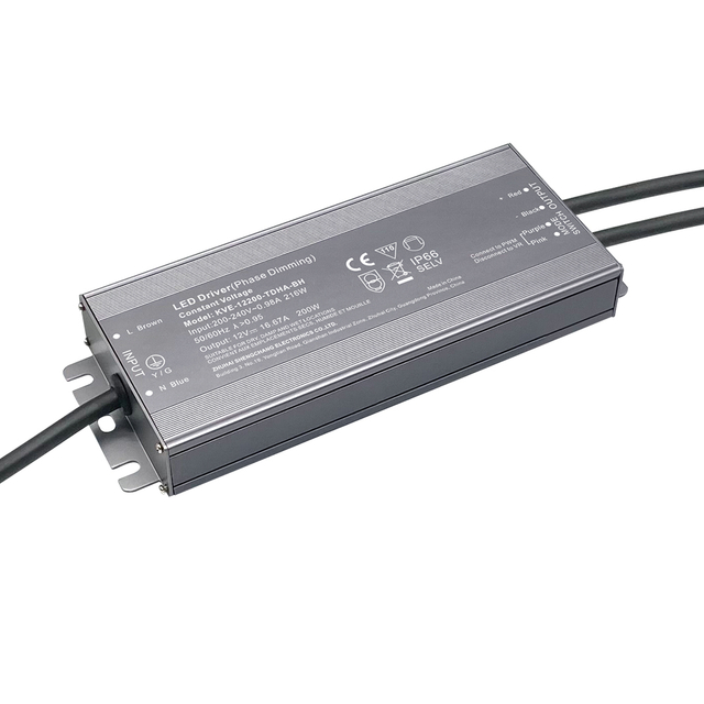
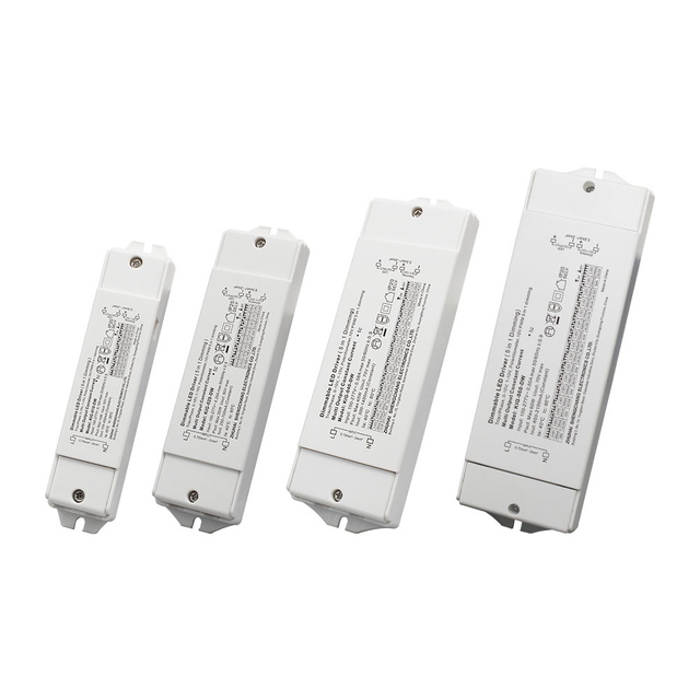
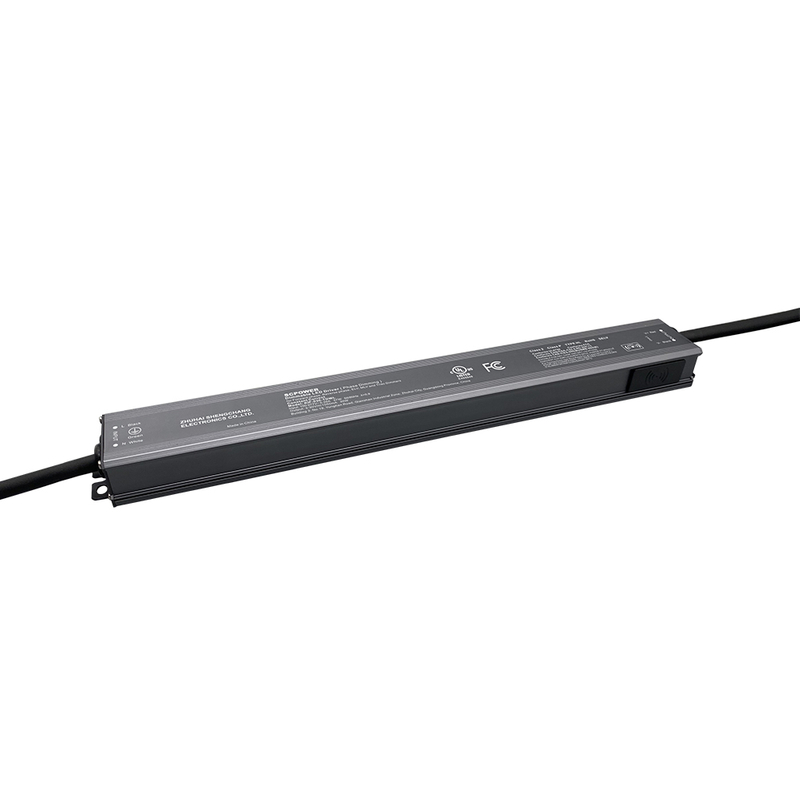
The LED driver serves as the critical bridge between the mains power supply and the diode array. The LED driver converts the incoming AC power into a regulated electrical output suitable for the LED load. Depending on the driver design, the output may be regulated as constant current (CC) or constant voltage (CV). During this rectification process, the driver must smooth out the electrical ripple inherent in alternating current. High-quality drivers utilize internal electrolytic capacitors and filtering circuits to flatten this ripple, ensuring a steady stream of power reaches the LEDs.
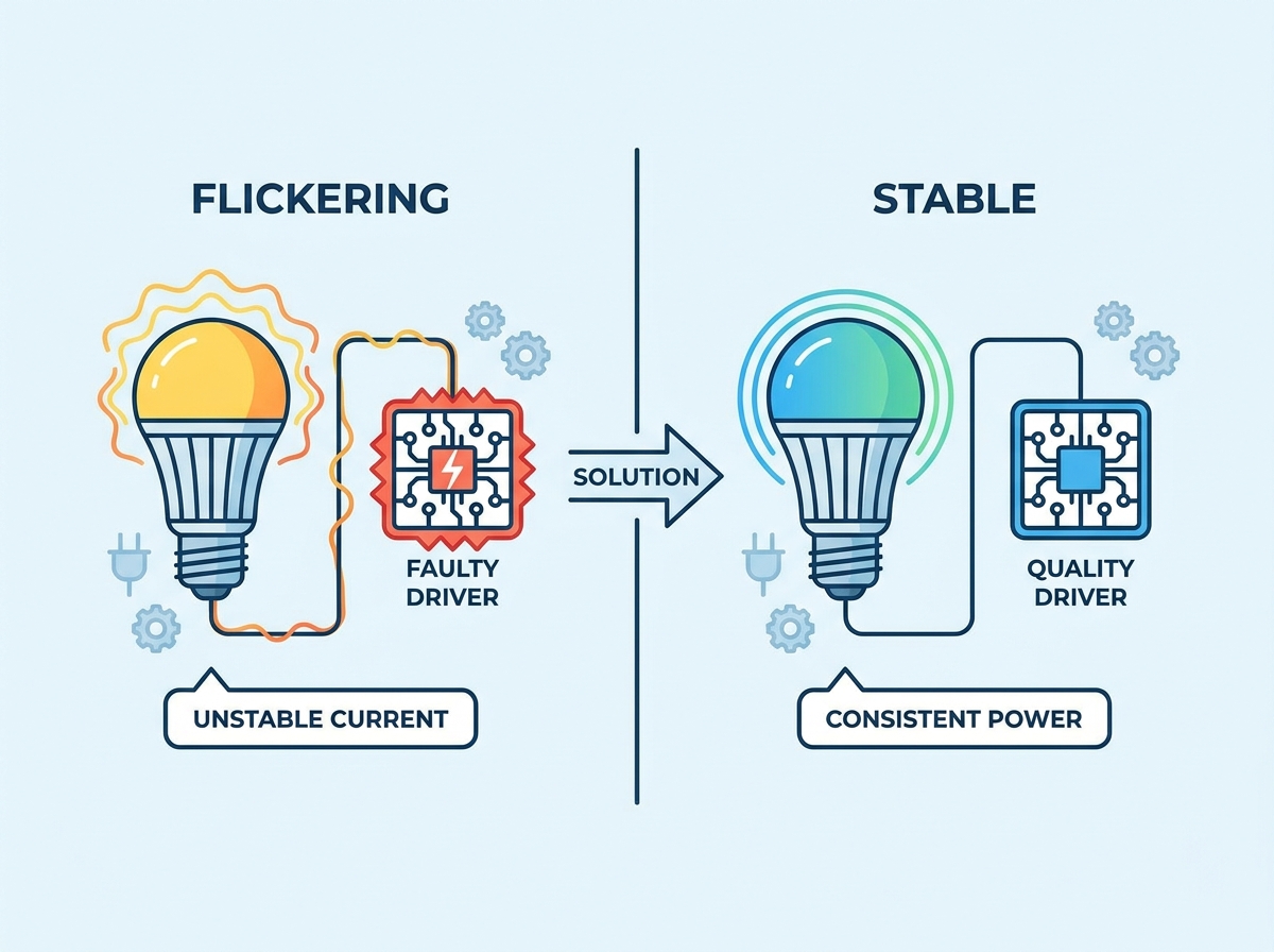
When a driver fails to smooth this electrical ripple, the voltage supplied to the diodes fluctuates rapidly. Because LEDs lack the thermal inertia of traditional incandescent filaments, they respond instantaneously to these voltage changes. A drop in voltage causes an immediate drop in light output. This rapid fluctuation manifests visibly as flickering, strobing, or erratic dimming behavior. If the driver cannot maintain the required operating conditions of the LED load, output current or light output may become unstable, resulting in visible flicker or intermittent operation.
Strobe vs. Visible Flicker vs. Intermittent Oscillation
Not all light modulation presents the same way in the field. Some forms of light modulation may not be readily visible to the naked eye but can still be relevant to visual comfort, camera imaging, or stroboscopic effects. The characteristics of the modulation depend on factors such as frequency, modulation depth, waveform, and operating conditions. Visible astable flickering operates at lower frequencies, usually between 3 Hz and 70 Hz, creating a highly distracting environment.
Intermittent oscillation refers to flickering that occurs only under specific conditions. The lights might remain stable at full brightness but oscillate wildly when dimmed below 50%. Alternatively, the flickering might only happen when heavy machinery powers on elsewhere in the facility. Categorizing the exact nature of the modulation helps isolate whether the root cause is environmental interference, control incompatibility, or internal component failure.
How to Diagnose LED Driver Problems That Cause Flickering
Evaluating the driver requires assessing both its physical state and its operational parameters. A failing driver often exhibits physical signs of thermal stress, such as bulging capacitors, cracked potting compound, or discolored housing. However, many failures remain hidden within the circuitry, requiring a systematic diagnostic approach to identify power delivery faults.
Faulty or Failing LED Drivers
The lifecycle of an LED driver heavily depends on its internal components. Electrolytic capacitors are particularly vulnerable to degradation over time. These components rely on a liquid electrolyte that slowly evaporates when exposed to continuous heat and extended operation hours. As the electrolyte dries out, the capacitor's Equivalent Series Resistance (ESR) increases. It loses its ability to store and release energy efficiently.
Once the internal capacitors degrade, the failing driver loses its capacity to maintain a constant current. The output voltage begins to sag and spike erratically. This inability to regulate power leads directly to voltage drops across the LED array, which the human eye perceives as a rapid, uncontrolled flicker. Replacing the degraded driver restores the necessary power regulation and eliminates the symptom entirely.
Undersized Drivers and Overloading
Driver capacity limits dictate the maximum electrical load a power supply can safely handle. Operating an LED load beyond the driver's specified output range can increase electrical and thermal stress and may cause protection functions, unstable operation, or reduced service life. If a lighting array demands 100 watts but is connected to an 80-watt driver, the power supply will operate in a constant state of overload. The driver pulls more current to compensate for the demand, generating excessive internal heat.
Excessive loading can increase internal temperature and may cause the driver to enter thermal protection, current limiting, or restart behavior. Modern drivers feature thermal protection circuits designed to prevent catastrophic failure. When the driver overheats, this circuit cuts the power, causing the lights to turn off. Once the components cool down, the circuit resets, and the lights turn back on. This continuous auto-shutoff and restart cycle appears to the end-user as a slow, deliberate flashing known as "hiccup mode."
Constant Current vs. Constant Voltage Mismatches
LED drivers are engineered in two distinct configurations: Constant Current (CC) and Constant Voltage (CV). Constant Current drivers vary the voltage across an electronic circuit to maintain a steady electrical current. They are typically used for high-power LED fixtures where diodes are wired in series. Constant Voltage drivers supply a fixed voltage, usually 12V or 24V, and are commonly used for parallel-wired applications like LED strip lighting.
Using a constant-current driver with a constant-voltage load, or vice versa, is an incorrect application and can result in improper operation, excessive current, insufficient output, or damage depending on the specific circuit design. The mismatch forces erratic power delivery, as the driver attempts to regulate a parameter the fixture is not designed to accept. This incompatibility results in aggressive flickering, failure to illuminate, or rapid component burnout due to overcurrent conditions. Always verify the specification label on the fixture before selecting a replacement driver.
Other Electrical Causes of LED Lights Flickering
Environmental and infrastructural variables frequently mimic internal driver failure. Even a brand-new, high-quality driver will fail to deliver stable illumination if the surrounding electrical infrastructure introduces noise, leakage, or severe voltage drops. Addressing these external factors is critical for system stability and long-term performance.
Incompatible Dimmer Switches
Many traditional phase-cut dimmers were originally designed around incandescent or halogen loads. LED drivers require compatible input-stage and dimming designs to work reliably with phase-cut control. These dimmers operate by chopping the AC voltage waveform, cutting off the leading edge of the sine wave to reduce the total power delivered to the bulb. Incandescent filaments cool slowly, masking the chopped power delivery.
Modern LED drivers process power differently. When an incompatible driver receives a chopped AC waveform from a TRIAC dimmer, its internal circuitry struggles to interpret the missing voltage. The driver's filtering components cannot smooth the aggressively altered wave, resulting in severe low-end flicker, strobing, or a complete failure to dim smoothly. Upgrading to drivers specifically designed and tested for TRIAC/phase-cut dimming can improve compatibility and reduce flicker. Replacing the dimmer with a compatible protocol may also improve system performance.
Smart Switches, Photocells, and Automated Controls
Automated lighting controls introduce unique electrical challenges. Illuminated smart switches, motion sensors, and photocells require a continuous power supply to maintain their internal electronics, even when the primary lighting circuit is switched off. In older wiring systems lacking a dedicated neutral wire, these devices pull their required operating power directly through the lighting circuit.
This creates a small but continuous leakage of standby current. The leaked current slowly charges the internal capacitors of the LED driver. Once the capacitor reaches a specific threshold, it attempts to fire the LEDs, resulting in a brief flash or strobe before immediately depleting its stored energy. The cycle then repeats, causing the lights to flicker rhythmically while the switch is in the off position. Depending on the control system, using a neutral-connected switch or an approved bypass/load device can reduce leakage-related ghosting or flashing. The solution should be selected according to the switch and driver manufacturer's compatibility requirements.
Voltage Fluctuations and Supply Frequency
Grid instability directly impacts the input stage of the LED driver. While high-quality drivers feature wide input voltage tolerances, severe fluctuations compromise their ability to maintain a stable DC output. Heavy industrial machinery, HVAC compressors, or large motors operating on the same electrical panel draw massive inrush currents upon startup.
These inrush currents cause temporary voltage sags across the local grid. If the supply voltage drops below the driver’s operational threshold, or if the supply frequency fluctuates significantly below 50/60 Hz, the driver cannot compensate fast enough. The resulting drop in output power causes the LEDs to dim momentarily or flicker until the grid voltage stabilizes. Dedicated lighting circuits isolate the drivers from these heavy industrial loads.
Loose Wiring, Joins, and Circuit Integrity
Physical infrastructure degradation bypasses the driver's regulation capabilities entirely. Loose wire nuts, degraded splices, or poor grounding at the fixture level interrupt the continuous flow of electricity. Thermal cycling causes wires to expand during the day and contract at night, slowly loosening mechanical connections over years of operation. Micro-arcing at these compromised connection points causes rapid, intermittent power loss.
This issue is particularly prevalent in linear or tape lighting installations. Degraded physical joins, poorly seated snap-connectors, or cold solder joints create high-resistance bottlenecks. As the connection shifts due to thermal expansion or physical vibration, the circuit breaks and reconnects rapidly. This causes specific sections of the LED run to flicker intermittently, even if the primary driver is functioning perfectly.
How to Fix Flickering LED Lights: Driver and Dimming Solutions
Resolving power regulation issues requires a structured decision matrix. Technicians must evaluate whether to replace individual components, upgrade the control system, or address facility-wide power quality. Implementing the correct solution prevents recurring maintenance costs and ensures long-term stability.
Component Replacement: Upgrading the LED Driver
Replacing the driver is often more cost-effective than replacing an entire high-bay or architectural fixture. When executing a component replacement, matching the exact specifications of the original driver is non-negotiable. The replacement must deliver the precise output voltage and output current required by the LED array. Check the existing driver label for the exact milliamp (mA) rating.
Furthermore, the new driver must provide adequate wattage overhead. Industry standards dictate a 20% buffer between the total wattage of the LED load and the maximum rated capacity of the driver. This overhead prevents the driver from operating at maximum capacity, significantly reducing thermal stress and extending the lifespan of the internal capacitors. Verifying the physical form factor ensures the new driver fits securely within the existing fixture housing or junction box.
System-Wide Upgrades: Matching Dimmers and Drivers
When incompatible dimming causes widespread flickering, a system-wide upgrade is necessary. Transitioning away from legacy phase-cut dimming to modern, low-voltage control protocols eliminates waveform chopping entirely. Protocols like 0-10V, DALI, or ELV dimming provide smooth, continuous control signals separate from the primary power delivery.
Consulting manufacturer compatibility matrices is mandatory before purchasing new dimmers and drivers. These matrices detail exactly which dimmer models have been bench-tested and certified to operate flawlessly with specific LED drivers. Ignoring compatibility charts often results in mismatched communication protocols, leading to dead travel on the dimmer slider, pop-on behavior, or immediate flickering at low dimming levels.
Dimming Protocol
Mechanism of Action
Flicker Risk Profile
Best Application
TRIAC (Leading-Edge)
Chops the front edge of the AC sine wave.
High Risk. Often incompatible with modern LED drivers.
Legacy incandescent retrofits where wiring cannot be changed.
ELV (Trailing-Edge)
Chops the back edge of the AC sine wave.
Moderate Risk. Smoother than TRIAC, requires compatible drivers.
Residential LED upgrades and low-voltage track lighting.
0-10V Analog
Uses a separate low-voltage control wire to set output.
If flickering persists across multiple independent circuits, facility-wide electrical issues are likely the culprit. Installing line conditioners or voltage regulators at the panel level smooths out grid instability and absorbs transient spikes before they reach the lighting circuits. Isolating lighting systems onto dedicated circuits prevents heavy machinery from causing inrush-related voltage sags.
Upgrading to drivers with higher input voltage tolerances provides an additional layer of defense. Universal drivers designed to accept a wide range of input voltages utilize more robust internal regulation circuitry. These drivers seamlessly compensate for minor grid fluctuations, maintaining a steady DC output even when the facility's power quality degrades momentarily.
How to Prevent LED Flicker After Driver Replacement or Upgrades
Executing repairs or upgrades without proper testing introduces new failure points. Balancing quick fixes against long-term reliability requires strict adherence to testing protocols, thermal management guidelines, and electrical safety standards.
Testing and Verification Protocols
Isolating the exact point of failure prevents unnecessary component purchases. Technicians must use digital multimeters to test the input voltage reaching the driver and the output voltage leaving it. If the input voltage fluctuates wildly, the fault lies with the mains power or the dimmer switch. If the input is stable but the DC output fluctuates, the driver has failed internally.
Verify the incoming line voltage at the fixture junction box using a True-RMS multimeter.
Inspect all wire nuts and push-in connectors for signs of thermal damage or loose seating.
Disconnect the dimming control wires to see if the flicker stops at full output.
Swap the suspect driver with a known-good unit of the exact same specification.
Measure the DC output voltage under load to confirm it matches the LED array requirements.
Bench-testing replacement drivers before full installation mitigates the risk of installing dead-on-arrival components. Connecting the new driver to a known working LED load on a test bench verifies its output stability and dimming compatibility before committing to the labor of a high-ceiling or complex fixture installation.
Thermal Management and Installation Realities
Heat is the primary enemy of electronic components. Installing new drivers in unventilated enclosures, tight ceiling cavities, or directly above heat-generating machinery guarantees premature failure. Every LED driver carries a maximum ambient temperature (Ta) rating and a maximum case temperature (Tc) point, specifying the hottest environment in which it can safely operate.
Exceeding the Ta rating accelerates the evaporation of the electrolytic capacitors, leading to rapid degradation and a return of flickering symptoms. Installers must ensure adequate airflow around the driver housing. In high-heat industrial environments, remote-mounting the drivers in a cooler, ventilated control panel extends their operational lifespan significantly.
Compliance and Electrical Safety Standards
Sourcing components that meet stringent safety standards protects the facility from fire hazards and liability. Select LED drivers that meet the applicable safety, EMC, and regulatory requirements for the target market. For North American applications, this may include relevant UL, CSA, or ETL requirements; European applications may require compliance with applicable EU directives and standards. These certifications and compliance measures help demonstrate that relevant safety and performance requirements have been evaluated.
Bypassing driver safety circuits to force a failing system to operate is a severe safety violation. Using non-compliant, uncertified components introduces significant electrical risks and may violate local electrical codes.
Conclusion
For projects that require stable power delivery and reliable dimming performance, Zhuhai Shengchang Electronics, founded in 2009, develops and manufactures intelligent dimmable LED drivers under the Suretron brand. Its portfolio includes dimmable LED drivers across a broad range of power levels, with solutions supporting control technologies such as DALI-2, D4i, TRIAC, 0/1-10V, DMX512, and selected wireless lighting-control protocols.
Audit your current dimming controls to identify legacy phase-cut switches that require upgrading to 0-10V or ELV protocols.
Use a True-RMS multimeter to test the DC output stability of any suspect drivers before discarding the entire LED fixture.
Verify that all replacement drivers possess a 20% wattage buffer to prevent thermal overloading and hiccup-mode flashing.
Install bypass resistors on circuits utilizing smart switches to eliminate standby current leakage and ghosting.
FAQ
Q: Why do my LED lights flicker only when dimmed?
A: This is usually caused by phase-cut dimmer incompatibility. Legacy dimmers chop the AC waveform, which modern drivers struggle to interpret at low levels. Upgrading to an ELV dimmer or a 0-10V dimming system resolves this by providing a smoother control signal.
Q: Why do my LED lights flicker when the switch is turned off?
A: Smart switches, dimmers, and photocells leak a small amount of standby current to stay powered. This leakage charges the driver's internal capacitor until it discharges, causing a brief flash. Installing a neutral wire or a bypass dummy load resistor absorbs this excess current.
Q: Can a failing LED driver cause a fire hazard?
A: Yes, if the driver lacks proper thermal protection. Overloaded or uncertified drivers can overheat, melting internal components. Always use UL-listed or CE-certified drivers, which contain built-in thermal shutoff circuits to prevent catastrophic failure and fire risks.
Q: How do I know if the problem is the LED driver or the bulb?
A: Isolate the issue by swapping a known working LED bulb or fixture onto the suspect driver. If the new bulb also flickers, the driver or the incoming power is at fault. If the new bulb operates perfectly, the original diode array has failed.
Q: What does it mean if my LED lights are flickering intermittently?
A: Intermittent flickering often points to external environmental factors. Heavy machinery starting up causes temporary voltage drops on the grid. Alternatively, loose wire nuts, degraded snap-connectors, or thermal expansion in the wiring can cause micro-arcing, breaking the circuit momentarily.
Q: Do I need a Constant Current or Constant Voltage driver to stop the flickering?
A: You must match the exact requirement of your fixture. Read the fixture's specification sheet. High-power fixtures usually require Constant Current, while LED strips require Constant Voltage. Mismatching these types guarantees erratic power delivery and severe flickering.
Q: How long should a high-quality LED driver last before flickering starts?
A: A commercial-grade LED driver typically features a Mean Time Between Failures of 50,000 to 100,000 hours. However, this lifespan drops significantly if the driver is installed in an unventilated area that exceeds its maximum ambient temperature rating.