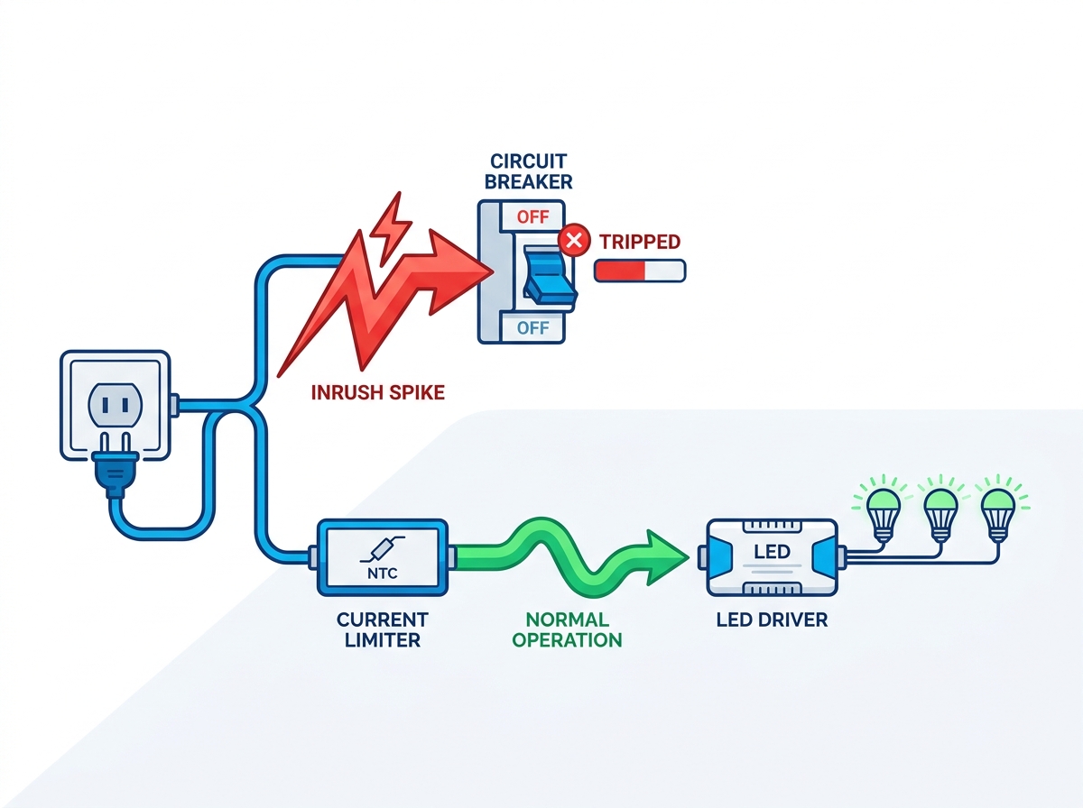
An LED lighting circuit can trip a circuit breaker during startup even when its steady-state load appears to be well within the circuit rating. One possible cause is input inrush current—the short-duration current drawn when the driver's input capacitors charge after power is applied.
Unlike the continuous operating current shown on a driver datasheet, inrush current is a transient event that can vary significantly with the driver's power architecture, input voltage, capacitance, power factor correction (PFC) design, switching topology, and the number of drivers energized simultaneously.
For large LED lighting installations, understanding this difference is important when selecting drivers, coordinating circuit breakers, and determining how many fixtures can share a branch circuit. This guide explains what causes LED driver inrush current, how to evaluate it, and which mitigation strategies can be considered when startup tripping occurs.
Key Takeaways
Inrush current is different from steady-state current: A driver may draw a short-duration current pulse at startup as its input capacitors charge.
Peak current alone is not enough: The peak magnitude, pulse duration, waveform, and number of drivers starting simultaneously all influence breaker coordination.
Breaker selection requires system-level coordination: The appropriate breaker depends on the driver's inrush characteristics, circuit impedance, wiring, breaker characteristics, and applicable electrical codes.
Manufacturer data is essential: When available, use the driver's measured inrush-current specification and manufacturer-provided breaker/fixture quantity recommendations.
Mitigation can be applied at several levels: Driver selection, circuit distribution, sequential startup, and dedicated inrush-limiting solutions can all be considered depending on the installation.
Table of Contents
Toggle
What Causes LED Driver Inrush Current?
The Anatomy of the Spike
Modern LED fixtures use an LED driver to convert AC mains power into regulated electrical output suitable for the LED load. Depending on the driver architecture, the input stage may include a rectifier, power factor correction circuitry, filtering components, and bulk capacitors.
When the input capacitors are initially uncharged, they can draw a high current pulse limited by the source impedance, rectifier, capacitor characteristics, and the driver's input-current limiting circuitry.
As the capacitors charge, the startup current decreases and the driver transitions toward normal steady-state operation. The magnitude and duration of this transient depend strongly on the driver's internal design and the electrical conditions at the point of connection.
This is why two LED drivers with similar rated wattage can have very different startup-current characteristics.
Ipeak and T50 Metrics
LED driver manufacturers may provide transient-current information using parameters such as peak inrush current and pulse duration.
Peak Current (Ipeak): The maximum current reached during the startup transient.
Pulse Width (T50): A commonly used measurement describing the period over which the transient remains above 50% of its peak value. The exact definition and reporting method should always be checked on the manufacturer's datasheet.
Breaker response cannot be determined from Ipeak alone. The magnitude, duration, waveform, source impedance, and the breaker’s time-current characteristics all influence whether a startup event causes a trip.
For this reason, LED driver inrush specifications should be evaluated together with the applicable breaker characteristics rather than using a single peak-current number as the deciding factor.
Steady-State vs. Transient Draw
Steady-state current and startup current describe different operating conditions.
A lighting circuit may remain within its normal continuous-load limits after all fixtures are operating while still experiencing a much larger short-duration current during simultaneous startup.
For example, a group of LED fixtures may have a relatively low combined steady-state current while still producing a substantial startup transient when all drivers are energized simultaneously. The actual allowable fixture count should therefore be determined using measured or manufacturer-specified inrush data and the breaker manufacturer's coordination information.
This distinction becomes especially important in commercial lighting systems where many LED drivers may be connected to the same branch circuit or energized from the same contactor.
Secondary Effects: Voltage Sags and Mixed Loads
A large simultaneous startup current can also produce a brief voltage drop when it flows through the impedance of the supply network and branch-circuit wiring.
The severity of the voltage sag depends on factors such as source impedance, cable length, conductor size, electrical distribution architecture, and the combined startup characteristics of the connected equipment.
Sensitive electronics connected to the same electrical system may be affected if the voltage disturbance is sufficiently large. For installations containing lighting together with control systems, network equipment, computers, or other sensitive loads, appropriate circuit distribution and electrical coordination should therefore be considered during system design.
How to Diagnose LED Breaker Tripping: Inrush Current or Electrical Fault?
Identifying Startup Tripping Patterns
A breaker that trips immediately when a group of LED fixtures is switched on may indicate a startup-current coordination problem, but inrush current should not automatically be assumed to be the cause.
The timing and repeatability of the trip can provide useful diagnostic information. For example, differences between a cold startup and a rapid restart may indicate that capacitor charging or an inrush-limiting component is influencing the behavior.
However, these observations alone do not prove that the driver is responsible. Wiring faults, insulation problems, incorrect breaker sizing, excessive steady-state load, incompatible controls, or other electrical problems should also be investigated.
Measurement Limitations
Short-duration startup-current events may be difficult to evaluate with a standard digital multimeter or general-purpose clamp meter because the instrument may not have sufficient bandwidth or sampling speed to capture the transient accurately.
For detailed waveform analysis, an oscilloscope and an appropriate current probe can be used to observe the startup event and measure parameters such as peak current and pulse duration.
Where field measurement is not practical, the driver's technical datasheet and manufacturer-provided breaker coordination information are usually the most useful starting points.
Leveraging Manufacturer Coordination Tables
Some LED driver and electrical equipment manufacturers provide coordination tables showing the recommended maximum number of specific drivers that can be connected to a particular breaker configuration.
These tables are especially useful because they consider the measured startup behavior of a specific driver rather than relying only on its steady-state wattage.
When this information is available, it should be used together with the breaker manufacturer's technical documentation and the applicable electrical design requirements.
Ruling Out Alternative Causes
Before attributing breaker tripping to LED driver inrush current, qualified electrical personnel should also verify the basic condition of the circuit.
Relevant checks may include:
Circuit insulation and wiring integrity: Verify that damaged insulation, ground faults, or wiring defects are not present.
Neutral and terminal connections: Loose or poorly terminated connections can create abnormal voltage behavior.
Steady-state current: Confirm that the normal operating current remains within the allowable circuit and breaker loading requirements.
Switches, relays, and dimmers: Ensure that control devices are compatible with the connected LED drivers and are rated for the intended load.
Breaker characteristics: Verify the breaker type, rating, manufacturer data, and applicable time-current characteristics.
Inrush-current analysis should be performed only after basic electrical faults and loading issues have been considered.
How to Reduce LED Driver Inrush Current: Breakers, ICLs and Soft Starts
Different installations may require different mitigation methods. There is no single solution that is appropriate for every LED lighting circuit.
Potential options include breaker coordination, lower-inrush LED drivers, load splitting, sequential startup, passive inrush limiting, active inrush-control circuits, and appropriate switching equipment.
Circuit Breaker Trip Characteristics
Miniature circuit breakers generally contain thermal protection for sustained overload conditions and magnetic or electromagnetic protection for short-duration high-current conditions.
Different breaker trip characteristics respond differently to short-duration startup currents. For IEC-style miniature circuit breakers, Type B, Type C, and Type D curves are commonly referenced.
IEC MCB Curve
Typical Instantaneous Trip Range
Type B
3–5 × In
Type C
5–10 × In
Type D
10–20 × In
These ranges describe typical instantaneous trip characteristics and should not be interpreted as automatic breaker recommendations for an LED lighting installation.
Breaker Characteristics and Inrush Coordination
Type B, C, and D trip curves are commonly referenced for IEC-style miniature circuit breakers. Their instantaneous magnetic trip ranges differ, but these classifications should not be treated as universal recommendations for every LED installation.
In North American projects, breaker selection should follow the requirements of the applicable electrical code, the breaker manufacturer's specifications, and the driver's documented inrush characteristics. A higher instantaneous trip threshold is not automatically a better solution.
Changing the breaker characteristic without checking the complete electrical system can affect protection coordination. Conductor sizing, fault-current availability, circuit impedance, equipment ratings, and local electrical requirements all need to be considered.
For this reason, a breaker change should be based on system-level electrical analysis rather than used as a general-purpose fix for LED startup tripping.
When Breaker Coordination May Be Appropriate
Breaker coordination may be useful in new installations or upgrades where engineers can evaluate the lighting drivers, circuit wiring, fault protection, and distribution equipment as a complete system.
If a different breaker characteristic is being considered, the selected device should remain compatible with the wiring, protection requirements, manufacturer's instructions, and applicable electrical code.
The goal is not simply to select a breaker that tolerates a larger current pulse. The goal is to ensure that normal startup events can occur while the circuit continues to provide the required overload and fault protection.
Installing Inrush Current Limiters and Soft-Start Solutions
In applications where changes to the distribution system are undesirable or impractical, dedicated inrush-control solutions may also be considered.
NTC Thermistors
Negative Temperature Coefficient (NTC) thermistors are commonly used as passive inrush-limiting components.
When cold, the thermistor has a relatively higher resistance, which helps limit the initial charging current. As current flows through the thermistor, it heats up and its resistance decreases significantly, reducing its effect on the normal operating current.
One limitation is its thermal recovery behavior.
If the power is removed and reapplied before the NTC has cooled sufficiently, its resistance may still be low, reducing its ability to limit the next inrush event.
For applications involving frequent switching or rapid power cycling, this characteristic should be considered when evaluating whether an NTC-based solution is appropriate.
Active Inrush-Control Circuits
Active inrush-control circuits can use controlled switching devices, resistive pre-charge paths, bypass relays, contactors, or other control architectures. The exact implementation varies by product.
Some systems initially restrict capacitor charging current and then bypass or reduce the limiting element once startup is complete. Other designs use semiconductor switching or more integrated control methods.
Because circuit architecture, reset behavior, thermal performance, and switching frequency can differ substantially between products, the selected solution should be evaluated using the manufacturer's specifications rather than assuming that all active soft-start devices operate in the same way.
Installation Considerations
Any external inrush-limiting device must be compatible with the LED driver's AC input, operating voltage, current rating, switching method, enclosure conditions, and applicable safety requirements.
The device should also be installed according to the manufacturer's instructions and applicable electrical regulations.
For line-voltage installations, installation or modification of branch-circuit wiring should be performed by appropriately qualified personnel.
Zero-Cross Switching Relays and Contactors
Zero-Cross Switching
Zero-cross switching closes an AC switching device near the zero-crossing point of the mains waveform. This can reduce switching stress and contact arcing in some applications.
However, zero-cross switching should not be treated as a universal inrush-current solution for LED drivers. The actual startup current is also determined by the driver's input capacitance, rectifier and PFC topology, source impedance, and internal inrush-limiting design.
For installations with significant startup-current concerns, use the driver's specified inrush-current data and verify the complete switching system through testing.
Evaluation Considerations
The suitability of zero-cross switching depends on the switching device, LED driver topology, mains characteristics, load configuration, and control architecture.
Solid-state or electronically controlled switching devices may also have different leakage-current, thermal, compatibility, and load-rating requirements compared with conventional mechanical contactors.
Therefore, zero-cross switching should be evaluated as one possible system-design technique rather than assumed to eliminate LED driver inrush current.
Best-Fit Applications
Zero-cross switching may be useful in some centralized lighting-control systems, automated buildings, or applications where reducing switching stress is beneficial.
Its effectiveness should nevertheless be verified with the actual LED drivers and switching equipment used in the project.
How to Control Inrush Current in Large LED Lighting Installations
Circuit Segregation and Load Splitting for High-Bay Drivers
Design Strategy
Large commercial lighting systems can place many LED drivers on the same branch circuit. In these installations, the maximum number of fixtures should not be determined from steady-state wattage alone.
Instead, designers should obtain the relevant startup-current data for the selected driver and compare it with the breaker manufacturer's characteristics or available coordination tables.
For example, if a manufacturer's coordination table specifies a maximum of 12 drivers for a particular breaker configuration, that published limit should be followed.
The lighting load can then be distributed across additional branch circuits where necessary.
Trade-Offs
Dividing the lighting system across more circuits may require additional breakers, conductors, control equipment, and installation labor.
However, appropriate circuit distribution can reduce the simultaneous startup demand placed on individual breakers and can improve overall system reliability.
The required balance between installation cost, available panel capacity, circuit layout, and startup performance should be evaluated during the electrical design stage.
Time-Delay Relays and Sequenced Power-Up
Design Strategy
Another approach is to avoid energizing all LED drivers simultaneously.
Lighting systems can be divided into zones and energized sequentially using lighting controllers, time-delay relays, contactors, building automation systems, or other suitable control equipment.
Instead of one large startup event, each group of drivers starts at a different time.
The appropriate delay interval depends on the driver startup characteristics, number of fixtures per zone, switching equipment, and overall control-system requirements.
Operational Outcomes
Sequential startup can reduce the number of drivers contributing to the same transient event.
This may improve breaker coordination and reduce the magnitude of system-wide startup disturbances, particularly in large warehouses, industrial buildings, stadiums, and other installations containing many high-power LED fixtures.
Sequencing should still be designed using actual driver and switching-system data rather than relying on a fixed delay value for every installation.
Which LED Inrush Current Solution Should You Choose?
Selecting a suitable strategy requires considering the existing electrical infrastructure, driver characteristics, number of fixtures, switching frequency, project cost, and applicable electrical requirements.
Mitigation Strategy
Typical Application
Key Considerations
Expected Effect
Breaker Coordination
New Builds / Electrical Upgrades
Requires evaluation of wiring, fault protection, breaker characteristics, and codes
Application-dependent
NTC Thermistors
Driver-Level / Simple Inrush Limiting
Passive and simple, but affected by temperature and restart interval
Moderate
Active Inrush-Control Solutions
Commercial / Specialized Systems
Product architecture and ratings vary
Potentially High
Zero-Cross Switching
Automated Lighting Systems
Effect depends on driver and switching topology
Application-dependent
Circuit Load Splitting
Large Lighting Installations
Requires additional circuits and distribution capacity
High when properly coordinated
Time-Delay Sequencing
High-Bay / Large Multi-Zone Systems
Requires control equipment and startup planning
High for reducing simultaneous startup
No row in this table should be interpreted as a universal recommendation. The most suitable solution depends on the actual equipment and electrical system.
Retrofit vs. New Build
New construction provides more flexibility because driver selection, branch circuits, switching equipment, and protective devices can be coordinated during the design stage.
Where startup current is expected to be important, designers can compare LED driver inrush specifications before finalizing the lighting and electrical architecture.
Retrofit projects may have more constraints because existing wiring, breakers, panel capacity, and control systems are already in place.
Depending on the installation, retrofit solutions may include using drivers with more suitable startup characteristics, redistributing fixtures across circuits, introducing staged startup, or using dedicated inrush-control equipment.
Breaker changes should only be considered when supported by the complete electrical design.
Procurement Criteria
Engineers, lighting designers, contractors, and buyers should review more than rated wattage and steady-state current when selecting LED drivers for large projects.
Where available, useful technical information includes:
Peak inrush current
Startup-current waveform
Pulse duration or T50
Test input voltage and test conditions
Maximum recommended driver quantity per breaker
Breaker manufacturer and breaker model used for coordination
Power factor correction architecture
Recommended switching devices
Restart behavior
Manufacturer application guidance
When a manufacturer provides measured inrush-current data and breaker coordination information, these values can help designers establish more realistic branch-circuit limits.
For projects involving many simultaneously switched LED drivers, selecting products with clearly documented startup characteristics can simplify electrical coordination before installation begins.
Conclusion
LED driver inrush current is a short-duration startup event and should not be evaluated in the same way as normal steady-state current.
When an LED lighting circuit trips during startup, begin by confirming that the circuit does not have an overload, wiring fault, incompatible control device, or other electrical problem. If inrush current is suspected, use the driver's measured startup-current specifications and the breaker manufacturer's coordination information whenever available.
For large installations, practical mitigation may include:
Selecting LED drivers with suitable documented inrush characteristics
Splitting large lighting loads across multiple circuits
Coordinating breakers with the complete electrical system
Verifying the design against applicable electrical requirements
A breaker should not be selected solely because it has a higher instantaneous trip threshold, and no single breaker curve or inrush-control technology is appropriate for every LED lighting installation.
For lighting projects that require reliable dimming performance, stable power delivery, and professional LED driver selection, Zhuhai Shengchang Electronics (SURETRON)specializes in the R&D, production, and sales of intelligent dimmable LED drivers and smart dimming solutions. Founded in Zhuhai in 2009, the company provides LED driver, controller, and power-conversion solutions for a wide range of lighting applications.
FAQ
What is the typical inrush current of an LED driver?
There is no single typical value that applies to all LED drivers. Inrush current depends on the driver's input architecture, power rating, input voltage, PFC design, capacitance, and internal current-limiting circuitry.
Always use the manufacturer's specified peak inrush current and pulse duration when designing the branch circuit.
Will a soft-start module stop my LED lights from tripping the breaker?
A suitable inrush-limiting or soft-start device may reduce startup current and help address nuisance tripping when inrush current is the confirmed cause.
However, performance depends on the device architecture, LED driver characteristics, total connected load, switching conditions, and breaker coordination. The underlying cause of the trip should be identified before selecting a mitigation device.
What type of circuit breaker is best for LED lighting circuits?
There is no single breaker type that is best for every LED lighting circuit.
For IEC-style miniature circuit breakers, Type B, C, and D curves have different instantaneous trip characteristics. The appropriate breaker should be selected based on the LED driver's documented inrush characteristics, breaker manufacturer's data, branch-circuit design, conductor sizing, fault protection requirements, and applicable electrical codes.
A higher instantaneous trip threshold should not be treated as an automatic solution to LED startup tripping.
How many LED drivers can I safely put on a single 15A or 20A circuit?
The maximum number should not be determined from steady-state wattage alone.
Use the manufacturer's breaker coordination table when available. It may specify the recommended maximum number of a particular driver model for a specific breaker and input-voltage configuration.
Steady-state loading, conductor requirements, electrical code limitations, switching equipment, and simultaneous startup behavior must also be considered.
Can LED driver inrush current cause voltage sags or affect sensitive electronics on the same circuit?
It can.
A sufficiently large startup current flowing through the impedance of the electrical supply and branch wiring can produce a short-duration voltage drop.
Whether other equipment is affected depends on the magnitude and duration of that voltage disturbance and the immunity of the connected equipment.
Where sensitive electronic equipment shares the electrical distribution system with large lighting loads, circuit segregation and startup coordination may be worth considering.
Does dimming an LED fixture affect its inrush current?
The answer depends on the LED driver and dimming architecture.
In many drivers, the primary startup-current event is associated with charging the input-stage capacitors and may occur independently of the commanded light output level.
However, different driver and control topologies can behave differently. Manufacturer data or testing should be used when startup-current behavior is important to the design.
What is the difference between inrush current and electrical surge current?
Inrush current is a startup current associated with energizing electrical equipment, such as the charging of input capacitors inside an LED driver.
An electrical surge generally refers to an externally generated transient overvoltage or disturbance, which may result from events such as switching operations or lightning-related transients.
Because the causes and protection methods are different, LED driver inrush-current coordination and surge protection should be evaluated separately.